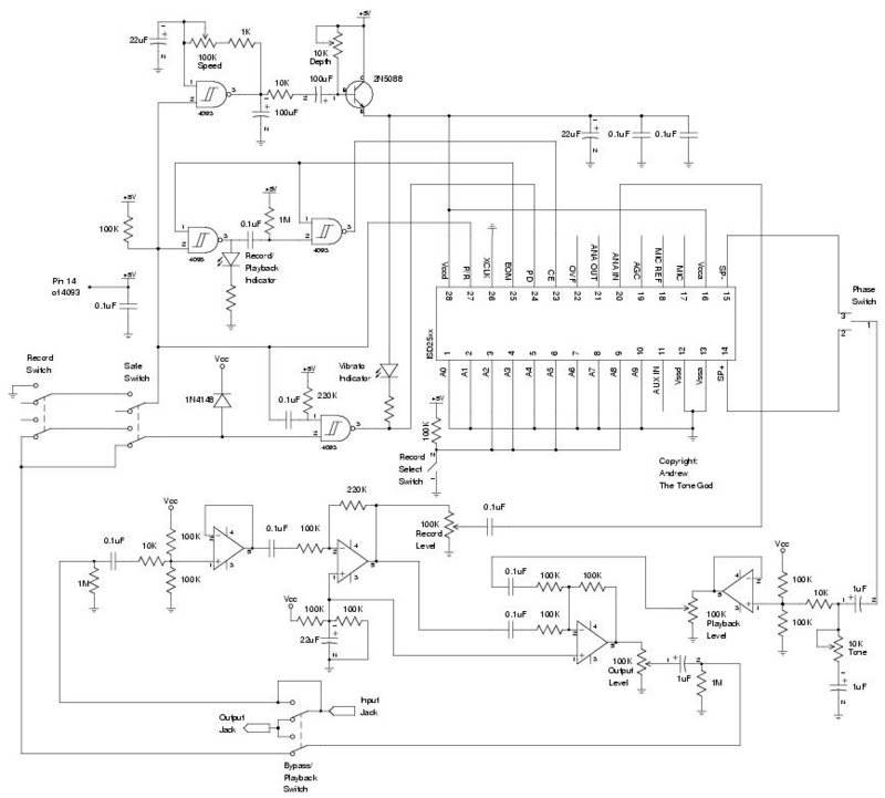
I have been playing with samplers in general for quite sometime but never really finished a design. Interest started to be generated in the DIY effect community about using a sampler for an effect so I decided to create and more importantly finish a design to be used as an effect. The design is what I call Payback (Figure 1).
Figure 1
Some of the features I was looking for in the Payback was to use a more current and modern IC and simplified record control so one would not have to do a tap dance to get the recordings working. I choose to ISD25xx series. They are easy to get and come in a large range of record time sizes.
Digital Control Logic
Control of the 25xx is done through digital logic. Some logic is included in the 25xx but compared to other recording families some logic has been removed. This is probably because the 25xx family is designed to be usable through either pushbutton and/or microcontroller. In order to maximize the ability of a microcontroller to control the 25xx while still making it possible for simple pushbutton control certain parts of the internal control logic is exposed. Our intention is to use the IC with pushbutton control so in order to regain some of the pushbutton functionality lost in the 25xx family we have to rebuild some of the control logic externally ourselves.
Control of the 25xx is done mainly through three inputs. Power Down (PD), Chip Enable (CE), and Playback/Record (P/R).
Operational Modes
I’m sure the first thing people think when flipping through the datasheets is the 25xx’s missing logic can be re-enabled through the use of the internal Operational Modes offered by the 25xx. Just enable the “Pushbutton” and “Looping” modes and your all set. Well this is partial true but I chose to not use any of the Operational Modes for a number of reasons.
Not all the required logic is available through the Operational Modes.
What logic offered through the Operational Modes can actually make the the rest of the external logic more difficult to implement.
Pushbutton mode activates extra debouncing circuitry that can slow down the response of the 25xx.
Operational Modes and message addressing functions are not available at the same time. This prevents the multiple recordings feature (mentioned in the Mods section)
When using the looping Operational Mode it always starts at 0 address. This would defeat the multiple recordings feature.
For the above reasons I choose to not use any Operational Modes but instead use the 25xx in default mode. The necessary external logic can be provided by a schmitt trigger NAND gate IC. Remember we are running the circuit 5 volts so other logic families can be substituted if needed as long as they behave logically the same. I used a CD4093.
Playback
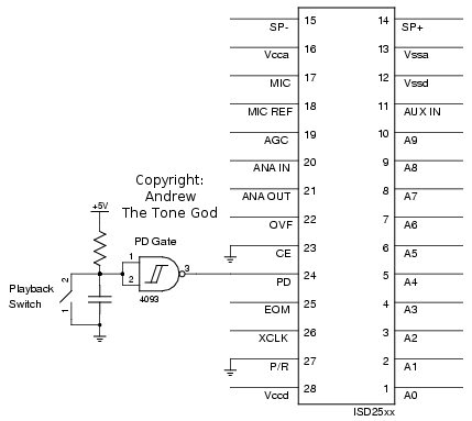
The default mode with the 25xx for CE in playback is edge-triggered (pulse). To start a playback the 25xx has to be brought out of power down, the P/R pin and address pins set, then the CE pin brought low to start the playback. When the 25xx comes out of power down it will read the CE pin. If the CE pin is already low when coming out of power down the P/R pin and address pins will be latched and the action set by the P/R pin, in this case playback, will commence without the need to pulse the CE pin (Figure 2). With this behaviour the PD pin can controlled the playback with a switch through a gate.
Figure 2
Looping Playback
If we want to loop the playback some extra logic is needed. We could toggle PD putting the 25xx in and out of sleep but it takes time for the 25xx to go to sleep then wake up and the sleep process will create noise on the output. A better way is to keep the 25xx awake and restart the playback.
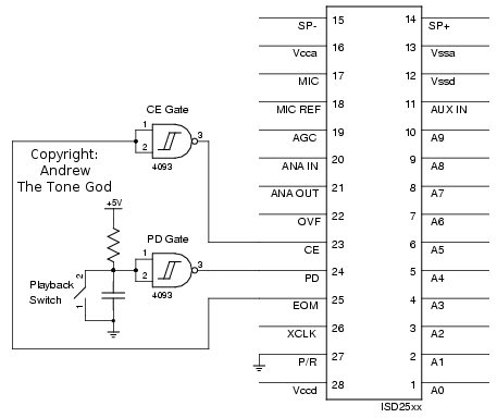
Playback starts when the CE pin is brought low. In order to restart the playback the CE pin needs to be brought high then low again at the end of the recording. The first problem is identifying when the recording ends. The 25xx has a output pin that indicates when the end of the recording is reached called the End Of Message (EOM) pin. The EOM output can be used to pulse the CE pin high and low causing the 25xx to re-latch the P/R and address pins starting the playback again from the beginning (Figure 3). The EOM pin is high on playback feeding it through the gate will invert it to the low level needed for the CE pin to start playback.
Figure 3
Recording
Starting the recording procedure is almost the same as playback but with two operational differences. The first is the CE pin is level triggered which means it is held low during the process instead of pulsed like with playback. This is not a big deal as the EOM output which feeds the CE gate stays high during recording so the CE gate holds CE low.
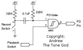
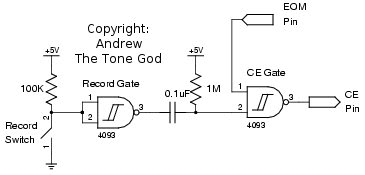
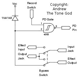
The second is the record cycle does not start if immediately if a playback cycle is occurring. If we attempted the recording process while a playback cycle was in progress we would have to wait until the playback cycle is finished. The only way to interrupt a playback cycle is to power down the 25xx. Afterwards we could power up the 25xx with the P/R and address pins set accordingly for recording. Putting a pulse detector on a input of the PD gate that is triggered when the record switch is hit will quickly put the 25xx in and out of power down thus stopping the playback (Figure 4). During the power down cycle the P/R and address pins can be set, P/R being set from the record switch itself, so when the 25xx is brought out of power up it starts recording immediately much like with playback.
Figure 4
Now that the record switch can Interrupt a playback cycle automatically it would be nice if the record switch could start the playback cycle again when leaving the record cycle. To start the playback cycle we can pulse CE like we do for looping the playback but instead do this when the record cycle is completed. We need to identify when the record cycle has ended.
Taking the record switch output, feeding it through a gate inverting the state, and using the gate’s output through another pulse detector will tell us when the record switch is switched off (Figure 5). The result of the record gate pulse detector is fed into the an input of the CE gate thus generating a pulse like that of a EOM pulse used for looping the playback. The generated pulse is long enough to allow the P/R pin to be set to playback mode from the record switch so when the pulse ends the 25xx will enter playback.
Figure 5
Analog
With the control of 25xx set lets look at how to get our audio signal in and out of the 25xx.
Input Buffer and Gain Stages
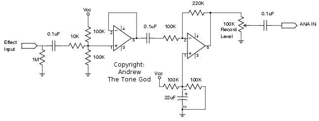
The input is pretty simple. The input signal enters the circuit through a non-inverting opamp buffer stage. The signal then goes through an inverting amplifying stage with the gain set at just over two (Figure 6). The output of this gain stage is used to feed two inputs.
Figure 6
The first is the Analog Input (ANA IN) of the 25xx. There is a pot on the input to adjust the input level allowing for the option of boasting lower signals or attenuating signals that maybe too large for the 25xx’s input. Of course you can also use it to drive the 25xx’s input into distortion for interesting effects but we would never do that around here would we ? 😉
The second path from the gain stage goes into the mixer stage which will be discussed below.
25xx Output Stage
Probably the toughest thing to do with the 25xx is to condition the output signal for our needs. The 25xx output is intended to drive a speaker which is not the signal type we need. There is no internal schematic of the output section to help so I tried several methods of interfacing the output. Only two worked well in my opinion.
The first was to take one speaker output and feed into an opamp buffer (Figure 7). This made use of the 25xx output stage in single-end operation which causes the output to deliver about 1/4 of the power. That is fine since anymore power would just mean we have to dissipate that extra power. Audio fidelity was good with this method as well.
Figure 7
The other method that seem to work we well was to use a transformer connecting the output to one coil and feeding the other coil to a opamp buffer stage (Figure 8). This resulted in a little more output but there was some fidelity loss. I used a telcom isolation transformer with a standard 600ohm:600ohm rating.
Figure 8
With good transformers being sometimes hard to find, costly, and large for some applications the direct method seems to work well.
Note: DO NOT CONNECT THE UNUSED SPEAKER OUTPUT! Leave it unconnected.
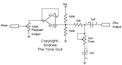
A simple tone control consisting of a capacitor with it’s ground connection varied through a pot is placed at the on the input of the 25xx output stage. You can use what ever tone control you like.
The 25xx output stage is fed through a pot to allow the adjustment of the 25xx output stage level.
Mixer Stage
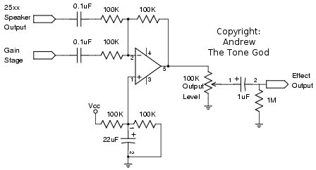
The final stage is a inverting mixer stage. One input signal is comes from the gain stage. The other input is from the 25xx output stage (Figure 9). With the 25xx output being adjustable the mix of straight signal from the gain stage and playback from the 25xx output stage allows the user the choice of lowering the playback signal below the straight signal, mix a similar amount, or have the playback be the dominate signal in the mix.
Figure 9
The mixer stage output is control by a pot to allow the user to adjust the final output volume. It does have some boast due to the gain stage.lit tellus, luctus nec ullamcorper mattis, pulvinar dapibus leo.
Modifications
There are a huge number of modifications one can make to this circuit. Here are some of what I would belive to be the more popular ones.
Playback/Bypass Switch
If you wish to use the bypass switch to also start the playback from the beginning and put the 25xx into power down when bypassed to save power this can be accomplished very easily.
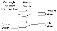
The first option is to use a 3PDT switch with one pole controlling the PD gate. The other option is to use the “leaky diode” trick used by many bypass indicator circuits to control the PD gate. This method only requires a DPDT switch and keeps the Playback/Bypass switch as true bypass (Figure 10).
Figure 10
Note: I choose to connect the diode to the 9v supply and not the 5v supply. The wire from the switch to the gate can become very sensitive to it’s environment particularly with the 5v supply. Using the 9v supply decreases the sensitivity of the wire connection.
Record During Bypass
To record while the effect is bypassed the 25xx has to be brought out of sleep. This can be done by use a DPDT switch with the second pole setting the PD gate either with a high signal or if you are using the Playback/Bypass switch mod you can put the switch pole in series with the control signal to disable the connection leaving the input high (Figure 11).
Figure 11
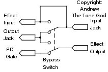
The other thing that needs to be done is to connect the audio signal/input jack to the circuit input (Figure 12). This will make the circuit non-true bypass but if you are using a high input impedance opamp, like the TL07x, there should not be an issue of the input being loaded down.vinar dapibus leo.
Figure 12
If it bothers you having the input connected all the time but sometimes you want to record during bypass you can put a switch in to disable the input connection.
Loop/Record Indicator
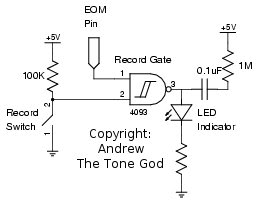
Creating a indicator to tell you when the effect is in record is easy enough. Connect an LED from record gate that feeds the pulse detector to the CE gate (Figure 13). The LED will turn on when you hit record. If you tie one of the record gate inputs to the EOM output you will also get a LED blink at the end of each playback loop.
Figure 13
Vibrato
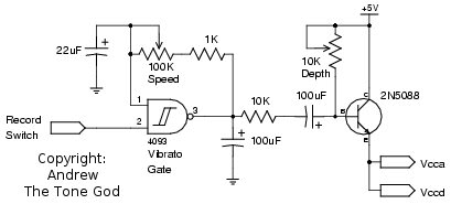
Adding alittle vibrato can really expanse the usefulness of this effect. The pitch of the play back can be varied by adjusting the voltage on the power supply feeding the 25xx. To vary the voltage an NPN transistor in series with the power supply is employed. The transistor’s base is biased high through a pot so the transistor conducts by default when no signal applied.
A clock is made from a spare logic gate. The output is smoothen out using a capacitor. This feeds another capacitor connected to the base of the transistor (Figure 14). When the clock goes low the capacitor starts to charge pulling the base low thus dropping the voltage to the 25xx. The rate of charging is controlled by the base bias pot which will act as a depth pot. This a very crude way to perform this function but it works and also provides a extreme range of settings.
lvinar dapibus leo.
Figure 14
The vibrato should not be active during record. One of the vibrato clock gate inputs is connected to the record switch. When the record switch is on the vibrato clock will be disabled. You could also hook up a switch up to this input and use it to enable the vibrato separately.
Pitch Shift / Slow Down Simulator
Using a pot instead of the clock could allow the manual adjusting of the voltage on the transistor base changing the speed of the 25xx and pitch of the recording. One could record at normal speed and slow down the playback dropping the original pitch. You could also record with the speed low then bring the speed up at playback raising the pitch of the original. You could even record at a middle speed and raise and low the speed and pitch. This control could be a rocker pedal.
Vibrato Indicator
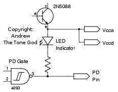
Connecting a LED from the 25xx power supply will allow you to see the speed and depth of the vibrato. Connecting the LED cathode to the PD input will turn the indicator on during operation and off when the 25xx is in power down thus it acts as a effect on indicator and vibrato indicator (Figure 15).
Figure 15
Safe Switch
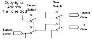
If you wish to prevent accidental recording the record switch can be disabled. Putting a switch pole in series with the record gate input will disable the record switch. If you have the record in bypass mode mod you can use another switch pole to re-enable the bypass function thus preventing the record switch from forcing the 25xx out of power down (Figure 16).
Figure 16
Multiple Recordings
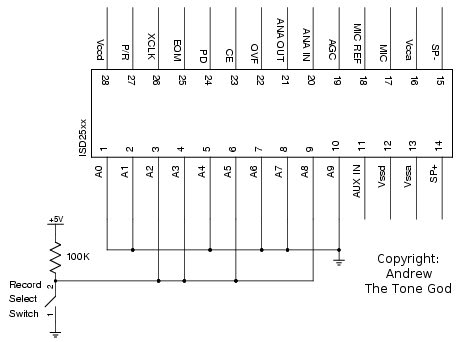
As mentioned earlier one of the reasons to use the default mode and not the Operational Modes was to have access to the address inputs. This allows the storing of multiple recordings in different parts of the memory which is nice since the 25xx comes in many large recording time sizes.
The memory in the 2532, 2540, 2548, and 2564 is split up into 320 address while the 2560, 2575, 2590, and 25120 is split up into 600 addresses. The address is latched when the CE pin goes low. The desired address is set using the address inputs in binary then the CE pin is brought low to latch the address and P/R inputs.
For example if we want to split a 2575 in half the address for the first half will be at decimal 0 which is 0000 0000 0000 in binary and the second address would be 300 decimal which is 00s01 0010 1100 in binary. Only four address pins are changing so a pull up resistor could be placed on those address pins with a SPST switch that connects to ground (Figure 17). When the switch is closed the first recording is selected when the switch is open the resistors pull the address pins high and select the second recording.
Figure 17
Since the address is only loaded when CE is brought low the recording will only be selected at the start of a record or playback cycle. If you select a different recording in the middle of the playback cycle the recording will continue playing until the end then start the selected recording. This can be nice if you want to mix different recordings and have them playback smoothly between each other.
You can create as many loops as there are addresses available but there is some things to be aware of. Just because you have decided where the recording boundaries are going to be the 25xx does not know about those boundaries. It will not stop the record cycle from going beyond your selected boundaries. If you decided you want the first recording space to be at 10 seconds long and another recording space 50 seconds long that is fine but when recording in the first space if you record beyond the 10 seconds to 15 seconds when you call the second space set at the 10 second mark you will get the 10 to 15 second portion of the first recording. Worse yet if you record starting from the start of the second space you will not only erase the 10-15 seconds of the first recording but you will delete the EOM marker for the first recording. When you play back the first recording the 25xx will playback the first 10 seconds of the first space/recording and continue playing back the second recording even past the 15 mark until it has hit the next EOM marker which would the end of the second recording.
The address pins can be control by various means such as internal dip switches, digital logic, multiplexer(s), etc. so there lots of options.
Phase Switch
We can invert the phase of the 25xx output which while by itself may not seem interesting when you start playing with the playback you can get different textures. Changing the phase is fairly simple.
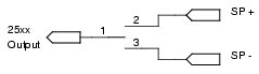
If you are using the direct connect method you can use the SP+ output for non-inverting and the SP- output for inverting. Switching between the two can be done with a SPDT switch (Figure 18).
If you are using the transformer method you can swap either side of the transform with DPDT switch (Figure 19).
Figure 18
Figure 19
25xx Recommendations
The 25xx comes in many different time sizes. The different times are achieved by the internal clock being set to different speeds from the factory. The different clock speeds create different sampling rates and cutoff frequencies. The shorter the time the faster the clock runs thus better sampling rates and higher cutoff frequencies which results in better fidelity. The longer the time the slower the clock thus lower sampling rates and lower cutoff frequencies causing lower fidelity. So while the longer times seem tempting the 25xx will suffer in audio performance.
If you are wanting to emulate the old ISD1420 which had a 6.4kHz sampling rate and 2.6kHz cutoff I would use either the 2540 with a 6.4kHz sampling rate and 2.7kHz cutoff or the 2575 with a 6.4kHz sampling rate and 2.7kHz cutoff.
Power Supply
You may have notice that this circuit needs a five volt power supply. You can decided for yourself what to use with the Power Supply – uC Have The Power article as guidance. Also pay attention to the decoupling portion of the article.
Digital Noise
There can be some noise from the logic/clock. Follow the noise reducing techniques mentioned in the Vanishing Point articles.
There you have it. The Payback looping sampler. Enjoy.