Recently we had a bad snow storm hit this area so since I was stuck at home I decided if I can do a project for a friend of mine.
A friend of mine wanted to switch between and drive at the same time two amps. He was using a passive A/B/Y box but complained of signal loss when driving both amps and noise when the other amp wasn’t being used. I suggested that I retrofit his passive box with a simple buffer circuit making it active thus the Super Y box was born. Get it ??? Super Y, Super Fly…ah never mind.
This could be done with any cheap stomp box as a means of building pedals without the need for doing metal work, chasing switches, etc.
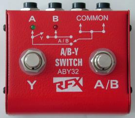
Here is the the box my friend was using. This provided a case, jacks, foot switches, LEDs, 9v compartment, feet, etc. all ready to go. (Figure 1)
Figure 1
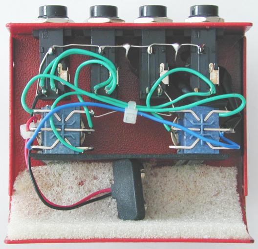
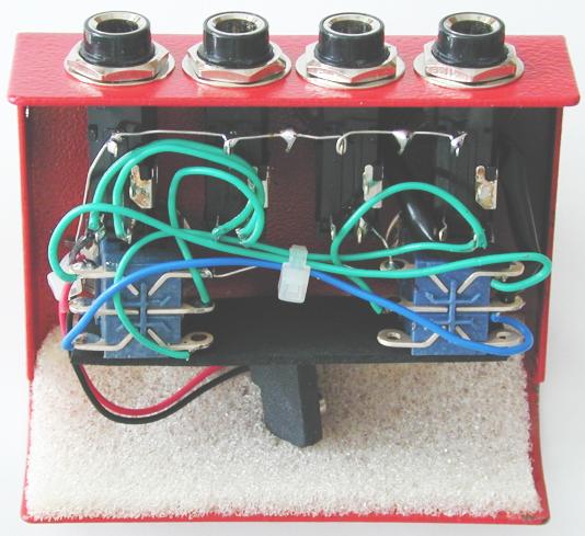
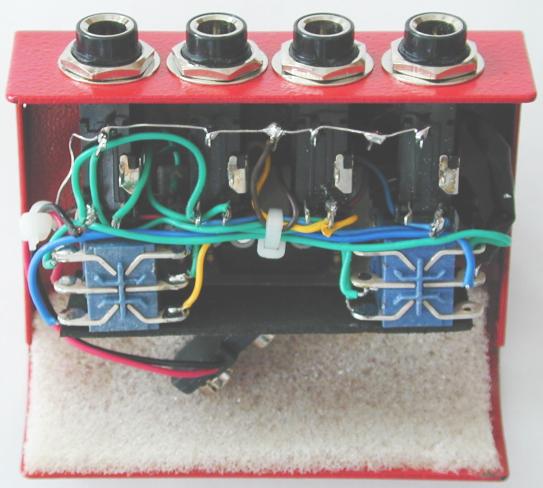
This is the box open showing you the wiring. (Figure 2 and 3)
Figure 2
Figure 3
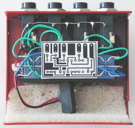
Checking to see if the board layout I just did will fit in the pedal cavity between the two foot switches. (Figure 4) I didn’t prototype the circuit as I knew it would work from doing similar circuits in the past. I did the board layout in less then 15 minutes.
Figure 4
Figure 5 is the original wiring layout of the pedal. Figure 6 is the wiring layout of the pedal with the Super Y. Sorry about the schematics. It is how you would say in french “Le Crappy”. I really have to build a new set of graphics for doing my schematics. To find out more about how the Super Y works check out the downloads area.
Figure 5
Figure 6
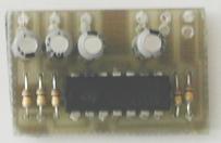
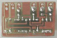
Here are the boards etched, drilled, and populated. (Figure 7 and 8) The whole process from circuit design in my head to a ready to go board took less then an hour. This goes to show that using bread boards is not always faster then circuit boards. You might recognize the board layout from the etching article.
Figure 7
Figure 8
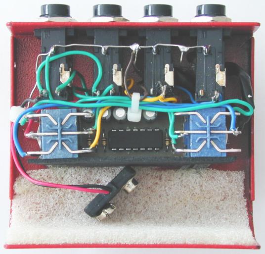
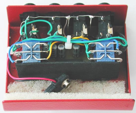
A few hours later this is what the insides looked like when I installed the board and rewired the pedal for the new board. You can see the board between the two blue foot switches. The board is being held in place by a piece of foam attached to the bottom of the board which is pushing the board against the collars of the switches. (Figures 9, 10, and 11)
Figure 9
Figure 10
Figure 11
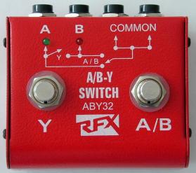
Here is the pedal completed. I wanted to keep it looking stock which I manage to do. (Figure 12) The whole project from conception to completion was completed within the snow day. Oh and yes the “untested” circuit did work perfectly. 🙂