Bullitt
Low Voltage Tube Tremolo
Introduction
Often when new people want to introduce themselves to the world of tubes they are scared of the high voltage and with good reason. Many people smartly try to use tubes at low voltage instead but the vast majority of low voltage tubes circuits are simple boasters and buffers. Lets do something more interesting while showing how tubes in different ways.
On of the effect most connect with tubes is tremolo. There have been many attempts to emulate tube amp style tremolo. I decided to come up with a tube tremolo effect that would operate similar to tube amp tremolos while having fun with tubes at a lower voltage.
Most tube amps use optocoupler based tremolos. We could have just grabbed a optocoupler or a FET, hook it up to a oscillator, and have it modulate a signal and that would be it. For me that would be boring and lazy besides getting proper optocouplers or FETs can sometimes be difficult and those are just extras parts that quite frankly we do not need. Some tubes amps used other non-optocoupler based tremolo circuits. One type would modulate the signal through the cathode of a stage. I choose to go with this method as it was simple and would not require extra parts compared to an optocoupler based tremolo.
Schematic
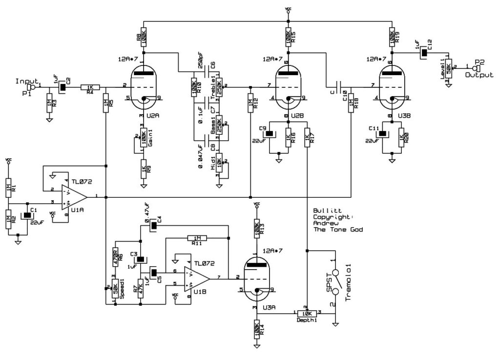
Figure 1
Audio Circuit
Lets go through the stages that make up the audio portion of the circuit.
Boaster Stage
Looking at the schematic for Bullitt (Figure 1) the tube first stage is a simple gain stage. There is a pot on the cathode that will adjust the gain of the stage. The range is quite wide. It will adjust the final output from less the unity, for if you are driving the effect with a boasted effect and you don’t want the tremolo to add any distortion, to a significant boast finally to a state when it will mildly distort so it could be used as a light distortion effect.
Tone Stack
The boaster stage feeds a Fender style tone stack which Fender used in many of it’s famous tube amps. It has the three common EQ controls being Treble, Mid, and Bass.
Modulation Stage
The tone stack feeds into another gain stage. This stage amplifies the signal helping to recover the signal loss that occurred in the tone stack. This stage’s gain is adjusted through the cathode much like the boaster stage but this time instead of a pot adjust the gain the signal from the oscillator is used to adjust the gain. This stage is what causes the attenuation of the signal.
Output Stage
The last stage is another gain stage fed from the modulation stage that connects to the Level control which adjusts the final output level of the effect.
Tremolo Circuit
Now lets look at the tremolo circuit.
Oscillator
One of the things I think makes tube amp tremolo sound like as it does is the oscillator circuit it uses. Unfortunately with the tubes running at low voltage a tube stage cannot generate enough gain to oscillate. Instead of trying to make something work with tubes I choose instead to replace the tube with an opamp still using the same phase shift oscillator circuit arrangement as tube amps use. This will preserve the “swing” of the tremolo that tube amp tremolo is known for. By using the opamp for the application the speed range of the oscillator can be extended as well.
Just to keep things clear I did not claim this was “pure” tube tremolo. I doubt anyone, atleast not those who are high priests of “mojo”, could argue that this changes the sound of the tremolo. The opamp is not in the signal path. The other opamp stage is used as 1/2 V+ voltage reference which feeds other parts of the circuit. The entire audio signal path is tube.
Oscillator Interface Stage
The output of the oscillator is connected to a tube stage which is configured as a cathode follower. This will prevent loading of the oscillator’s output and provide signal conditioning to interface the oscillator’s output to the modulation stage. The amount signal modulation signal is varied through the Depth control.
The tremolo can be turned off by connecting the Depth control to ground using a SPST switch. Using the Tremolo Switch will turn the effect into a buffer/boaster/distortion.
Power Supply
This circuit is configured for a power supply running at 12 volts. Both tube heaters are run from this supply as well as the other circuitry. The tube heaters will need 300mA. There will also be some extra current needed for the rest of the circuit. A 500mA supply should be plenty and easy to find.
If you are using a 12VDC adaptor make sure it is well regulated and well filtered. If it is not you have to do so yourself. I would suggest using a 15VDC 500mA adaptor running through a voltage regulator like a 7812 with proper filtering. That should supply the circuit adequately
Mods
The circuit is very open to modifications. Some examples would be:
- Switchable gain levels but using a SPDT switch on the cathode of the boast stage and select between two Gain controls.
- Half/Double speed switch buy using a dual gang pot and switching them in and out of parallel using a SPST switch thus halving/doubling the resistance of the Speed control.
- Hard/Soft Switch using a SPDT throw switch to switch between two Depth pots.