Payback v1.1
Looping Sampler
Introduction
I dislike effect projects based on out of date parts so when the announcement from Winbond that the ISD2500 series Payback v1.0 is based on was going to be discontinued it was time to redesign Payback to use a newer current IC family. This also allowed a chance to improve on a few things with Payback v1.0 that people commented on so I would like to introduce Payback v1.1 (Figure 1).
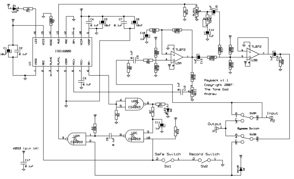
Figure 1
As of this time there are not many options when it comes to current production recorder IC families that both fit our needs and are DIY friendly. I choose to go with the ISD1600B family for these reasons:
- The IC is in the 16-pin 300mil (narrow) DIP format. A much welcome size improvement over the huge 28-pin 600mil (Wide) DIP.
- Pushbutton control logic is included internally simplifying some of the logic needed.
- Direct analog output available. No more issues with interfacing to the internal speaker amplifier.
- The builder can select the oscillator frequency thus the sampling rate and recording time available instead of being forced to use an IC with a fixed settings.
- Different length versions available. When combined with the user’s ability to set the sampling rate this allows the builder to design what record time and sample rate they wish to have.
- Having access to the oscillator makes for an easier method of achieving vibrato.
- Capable of running at lower voltages (2.4v – 5.5v) extending battery life usage.
- Cheaper. The price different between versions is very little.
Of course there are some draw backs to the IC family change which include:
- While some control logic is included some important logic is not. This logic needs to be recreated, in some cases by unusual means.
- No analog input. Only the MIC inputs are available.
- The recording lengths are not as long as those available from the ISD2500 family.
- No multiple messages. Only one recording.
- No backwards compatibility with Payback v1.0 or other looping samplers.
Many of the draw backs that directly affect the operation of the circuit can be addressed allowing us to still build a circuit for our needs. Many of the same principals of Payback v1.0 still apply so be sure to read that article as well to understand the operating principals better.
Analog
Payback v1.0 analog section was fairly large and complex due to it needing to perform various functions including interfacing. With this version I attempted shrink down the analog section to make it simpler while still keeping most of the important features. If you want any of the features or are trying to retrofit you can still use the Payback v1.0 analog section.
I decided this time around to not have a boasted output with the final output level adjustable. Instead I aimed to have the output be near unity with the input signal while the playback level is still adjustable. This removes output level control from the circuit.
Input Stage
The input signal gets fed through a non-inverting gain stage (Figure 2). This stage serves a few purposes. The first is that it provides a high impedance input buffer. This stage also amplifies the signal to be fed into the mixing stage and the ISD1600B for recording with the record level being adjustable using the record level pot. The gain level has been set to overcome the losses accumulated on the way to the output giving the straight through signal near unity on the output. You should not be able to notice any major signal level change between the bypass clean signal and the effect clean signal levels.
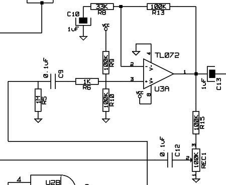
Figure 2
Unlike the ISD2500 which had an analog input the ISD1600B does not have this input. The inputs are configured for a microphone and not for a standard input signal. This requires a few changes. The unused input (MIC-, pin 7) needs to be decoupled to ground to disable the noise cancellation feature which could interfer with our recording. The signal from the input stage can be fed into the other input (MIC+, pin 6).
The microphone inputs also have an Automatic Gain Control (AGC) feature that adjusts the gain of the internal preamplifier to compensate for different input levels that a microphone would encounter. This feature needs to be disabled so it does not interfer with our recording. The AGC response is set through the AGC pin (pin 12). Connecting this pin to ground not only disables the AGC feature but also sets the internal preamp to it’s highest gain level which reduces the need to amplify the signal from the input stage any further (Figure 3).
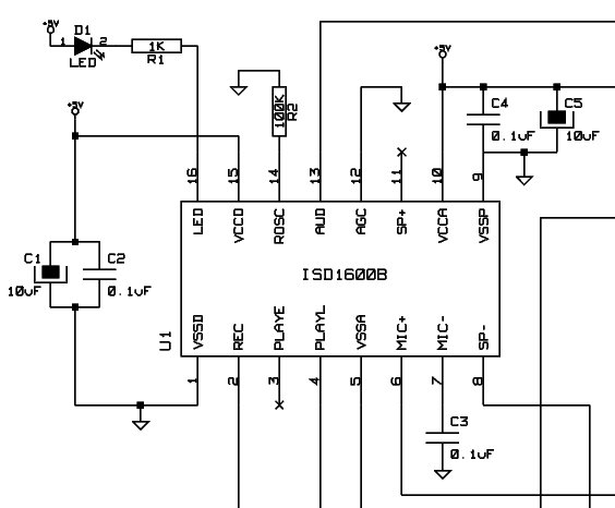
Figure 3
Output Stage
In previous ISD based looping sampler ICs the output signal was derived from the internal speaker amplifier. The problem with this is the amplifier was not intended to used for preamp signal levels, it was intended to drive a speaker directly. Various tactics had to be employed to make the amplifier work sometimes with undesirable results. Furthermore these ICs employed a class AB amplifier output stage to drive the speaker. Newer ICs are coming with class D output stages which are generally undesirable for our needs.
Luckily the ISD1600B has a separate audio output, AUD (pin 13). This pin is not to serve as a preamp output but intended to drive an external amplifier. To work it needs to be loaded which can be done with a 1K resistor to ground. The output can then be fed into the mixer stage.
The output stage is a basic non-inverter buffer stage (Figure 4) but much like the input stage the output stage is performing a few different functions at once. Instead of having a dedicate mixing stage like with Payback v1.0 I went with a more primitive resistor mixer feeding into the output stage. The added gain of the clean signal from the input stage and the AUD output which is boasted from the internal amplifier helps overcome the loss of the mixing stage. The playback signal to clean signal can be adjusted to taste with playback level control. A simple tone control is attached to the playback signal path which rolls off high end.
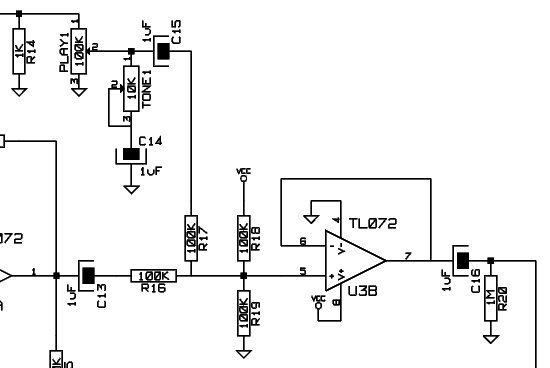
Figure 4
Digital Control Logic
The ISD2500 series exposed alot it’s internal control logic to give the designer flexibility in determining the behaviour of the IC. The ISD1600B family on the other hand is designed to fit a specific need. To fulfill this need some features have been included and some removed to make the designer’s life easier. We are using the ISD1600B in somewhat of an unusual manner from what the IC is designed for so some of the features are a nice addition while others make things difficult as you will see.
One of the nice new features is the control logic for playback and recording operations. Unlike with the ISD2500 where we had to set various pins to the needed state the ISD1600B has pushbutton control logic. This is logic that requires little or no extra parts other then the switch itself to operate.
Playback
All that is needed to start a playback cycle is to ground the playback pin using a switch (Figure 5). There are two playback pins included, PLAYE (pin 3) and PLAYL (pin 4), which are intended to be used depending if the playback switch is toggle or momentary. PLAYE is an edge triggered input that starts and continues playing back the whole loop when pulled low even if the input is goes high during the playback. PLAYL plays the loop when held low. If the input goes high during playback it will stop the loop and start from the beginning when pulled low again. I choose to use the PLAYL input because the playback can be interupted and restarted from the beginning on demand instead of waiting for the loop to end as with the PLAYE input. This is handy if you need to sync the playback to something.
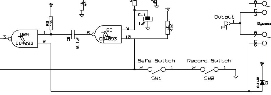
Figure 5
Looping Playback
Up until now the control logic was smooth sailing but you should know by now that when things seem to be too good to be true you will get hit with something big. Here it is.
The ISD1600B has no facilities for looping the playback. There are no internal modes to perform this function. There are no logic outputs that signal the end of playback. The only logic output available is the LED output but unlike previous ICs during playback the LED consistently blinks giving no clear indication when the sample ends so it is not very useful for knowing when the playback has ended.
The only other outputs on IC are the audio outputs. If there was some way to monitor the audio output we could find out when the loop ends but the audio output is not logic based. Time to pull out one of my dirty tricks.
Reading through the datasheet tells us that when playback ends the IC goes into shutdown putting the AUD and SP+/- outputs into tri-state which basically means the pins are left floating. If we set the output to a known state that is opposite to when it is active we will know when the output is active playing back a sample or if the playback operation has stopped. We are already using the AUD pin for our audio output so it might be better to use one of the speaker outputs, SP+ (pin 11) and SP- (pin 8), to prevent interfering with the AUD output. I choose to use the SP- speaker output.
There is an added advantage to using a speaker output. Remember the speaker amplifier is now class D which uses PWM. For our purposes the important thing to know about PWM is that it switches between full high and low states very fast. The amplifier uses the same voltage supply as the logic so the high amplifier state is the same voltage as the high logic state. The high output can override a pull down resistor, say 1K, serving as a dummy load on the output thus giving us a high signal when a playback is happening. When inactive the pull down resistor can set the output low. The speaker output then can now be fed into a logic gate to indicate activity.
There is still a problem. The PWM output switches between high and low states quickly causing the gate to switch between states quickly as well. This is not giving us the clean high or low states indicating if playback is in progress or not that we need. This problem can be solved easily enough. Using the speaker logic gate as a buffer the output can be put through a RC filter network to smoothen out the output giving us nice clean high and low outputs indicating operation. There is an LED used on the speaker gate output to limit the signal. The LED can be just about any type.
This clean output from the playback gate can now be fed into a pulse detector creating a trigger gate to retrigger the PLAYL input thus restarting the playback (Figure 6). We now have a looping sampler.
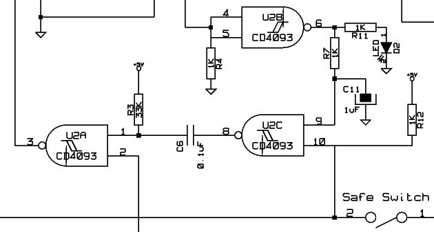
Figure 6
Recording
To start a record cycle the REC input (pin 2) is connected to ground through the record switch. The recording process continues as long as the input is grounded. When the switch opens breaking the ground connection a 1K resistor sets the input high stopping the recording cycle. The switch can be a simple SPST switch.
Taking the REC input from the record switch and feeding it into the playback gate (Figure 7) will cause a pulse to be generated when a record cycle has stopped just as with the end of a playback cycle. If the effect is already engaged this pulse will automatically restart the IC in playback mode when the record cycle has ended.
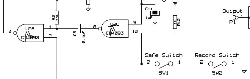
Figure 7
Modifications
Here are some of the more popular modification for Payback v1.1.
Playback/Bypass Switch
A common modification was to use the bypass switch to also control the playback. This can be done in a similar way that Payback v1.0 did by making use of the “leaky diode” trick again on the trigger gate the controls the PLAYL input. The bypass switch can be a DPDT switch while still being true bypass. You can use a 3PDT switch with one pole grounding the gate input and a pull up resistor on the PLAYL pin and leave the diode out if you wish.
Note: I choose to connect the diode to the 9v supply and not the 5v supply. The wire from the switch to the gate can become very sensitive to it’s environment particularly with the 5v supply. Using the 9v supply decreases the sensitivity of the wire connection.
Record During Bypass
Another common modification is to be able to record while the effect is in bypass. Connecting the input signal to the input stage during bypass will provide this feature. If you use a good opamp (like the TL072) the input stage will be high impedance so it should not load down the input signal in any significant manner. If it bothers you having the input connected all the time but sometimes you want to record during bypass you can put a switch in to disable the input connection.
Note: If you want to be able record in bypass do not use the true bypass configuration that grounds the effect input.
Loop/Record Indicator
Many people like to have an LED indicator to know what is going on with the effect. We could do something similar from Payback v1.0 which is use a logic gate output for the LED indicator. I think it would be easier to just use the LED indicator output (pin 16) that comes with the ISD1600B. It goes solid when recording, blinks during playback, and is off when not operating. That should be plenty of information for the average user.
Safe Switch
A safe switch that prevents recording can be made simply by putting a switch in series with the record switch.
Vibrato
Some people like adding vibrato to the playback. In Payback v1.0 the vibrato was achieved by adjusting the voltage to the ISD2500 on playback. I suspect that varying the voltage supply caused a change to the internal clock speed changing the speed of the playback and with it the pitch much like a record player. The problem with the doing vibrato with this method is if you drop the voltage too much you can cause the IC to fail. Furthermore because the vibrato circuit is part of the power supply if you did not get the vibrato to work properly the IC may not get power at all and fail completely.
With the ISD1600B the clock is set externally through the Rosc input (pin 14) with a resistor to ground. Adjusting the relationship to ground changes the clock speed. No more messing around with the power supply. Connecting a clock source to the Rosc input altering the voltage will change the clock speed and pitch of the playback. You can use a clock source of your choice and set it to you tastes. Putting a pot in parallel will vary how far the clock source can sweep giving us a depth control.
It would be a good idea to disable the vibrato during recording. Using a spare NAND gate from the 4093 with it’s inputs connected to the REC pin you can drive a NPN transistor to ground the clock resistor connection overriding the clock source (Figure 8).
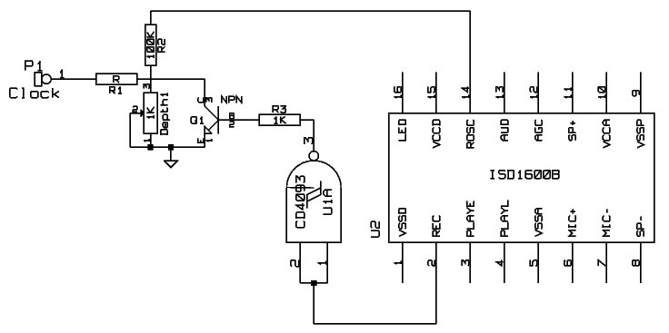
Figure 8
ISD16xxB Recommendations
The ISD1600B comes in a few different versions. ISD1610B, ISD1612B, ISD1616B, ISD1620B. The last two digits indicate the recording length of the IC when running at 8KHz. You can slow down the clock to get more time but at the loss of a lower sampling rate. If you want higher quality recording you can raise the clock speed and use a longer version. As of this writing the cost of a ISD1610B is alittle over $5 CDN and the cost of a ISD1620B almost $7 CDN. With the price difference of only a few dollars it should not be much of an issue if you wish to go bigger.
You can decided what IC version and resistor value to use for the oscillator with the following charts. If you wish to emulate the old ISD1420 which runs at 6.4KHz for a total of 20 seconds you can use the ISD1616B with the clock resistor set at 100K.
| Sampling Frequency | 12KHz | 8KHz | 6.4KHz | 5.3KHz | 4KHz |
| ISD1610B | 6.6 seconds | 10 seconds | 12.5 seconds | 15 seconds | 20 seconds |
| ISD1612B | 8 seconds | 12 seconds | 15 seconds | 18 seconds | 24 seconds |
| ISD1616B | 10.6 seconds | 16 seconds | 20 seconds | 24 seconds | 32 seconds |
| ISD1620B | 13.3 seconds | 20 seconds | 25 seconds | 30 seconds | 40 seconds |
| Sampling Frequency | 12KHz | 8KHz | 6.4KHz | 5.3KHz | 4KHz |
| Rosc | 53K | 80K | 100K | 120K | 160K |
Power Supply
You may have notice that this circuit needs a five volt power supply. You can decided for yourself what to use with the Power Supply – uC Have The Power article as guidance. Also pay attention to the decoupling portion of the article.
Digital Noise
There can be some noise from the logic/clock. Follow the noise reducing techniques mentioned in the Vanishing Point articles.
I think Payback v1.1 is a nice iteration of this design that I think many will appreciate. Enjoy.