Rock N' Control
Controlling Effects from Remote Locations
Intro
Its always fun finding new ways to use existing effects. Adding an external expression pedal is one thing you can do to add a new dimission to an effect you already own. Univibe owners can attest to the fun of being able to control the speed on the fly. You can control the speed of your tremolo, the repeats of your digital delay, or whatever you want. The choice is yours.
Adding external control is one thing but controlling it from long distances is another. Sending effect signals over long distances can cause problems. It is best to leave your effect signals inside the box and control it via some mechanism that isolates the effect signal from the control source. The simplest option is use a optocoupler.
Opto-Wha ?!?
Optocoupler is a fancy name for something that is really simple. A definition for an optocoupler is a device that uses one signal to control another while maintaining the electrical isolation of the signals optically. A simple optocoupler for our use is an LED pointing into a Light Dependent Resistor (LDR). A LDR is a device that changes it’s resistance when the amount of light it is exposed to changes. A light controlled resistor. The LED provides the light source for the LDR to respond to. By controlling the LED brightness we can control the signal connected to the LDR.
Now we can work on controlling the LED knowing that the effect signals are safe in the the box. Controlling the LED is pretty a simple which is a good thing…well at least for me.
Catching a Wavelength
LDRs do not respond to all colours the same way. Depending on what colour the LDR is exposed to it may not operate to it’s full specified resistive range. The simple answer would be to use true pure white light since it contains all the colours but this is difficult and expensive. A better answer would be to use a light source of a colour that the LDR will respond to fully. Which colour depends on what material the LDR uses. The most common materials used in LDRs are cadmium sulphide (CdS) and cadmium selenide (CdSe). You can see how each material responds to changing colour differently (Graph 1). You can use the colour spectrum below (Graph 2) to help you related the wavelength to colour.
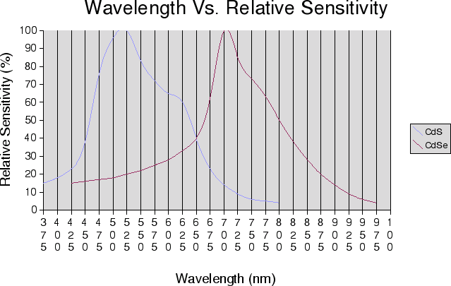
Graph 1
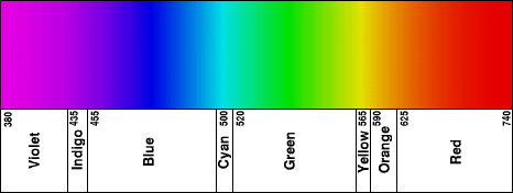
Graph 2
LDRs do not respond to all colours the same way. Depending on what colour the LDR is exposed to it may not operate to it’s full specified resistive range. The simple answer would be to use true pure white light since it contains all the colours but this is difficult and expensive. A better answer would be to use a light source of a colour that the LDR will respond to fully. Which colour depends on what material the LDR uses. The most common materials used in LDRs are cadmium sulphide (CdS) and cadmium selenide (CdSe). You can see how each material responds to changing colour differently (Graph 1). You can use the colour spectrum below (Graph 2) to help you related the wavelength to colour.
Switching
Optocouplers have been used for simple on-off switching signals. Some amps use them for channel switching (Music Man, Fender, etc.) and I belive some effect companies use them as well (Morley ?). This is fine for small signals and easy enough to do but there are better ways of doing this function using modern technology. Needless to say this would not the best way of doing things if you are dealing with larger signals.
Expression Control
By expression control we are talking about the ability to continually control a signal in real time. This is achieved in our situation by adjusting the LED’s brightness with the rocker pedal thus changing the LDR’s resistance which the effect parameter is controlled through. This is simple enough but there are some issues we have to look at before we start hacking up our beloved effects.
Rock N' Control (2 Pole)
The optocoupler in this configuration can only work as a serial resistor. The parameter you wish to control must use the pot as a serial resistor. Try to find a schematic of your effect. Look at the parameter’s pot that you want to control. It should use one the following symbols (Figure 1). If all three lugs of the pot have separate electrical connections then this method of control will not work.

Figure 1
It is necessary that the resistive range of the parameter you want control is taken in to consideration. If you can, use a LDR that matches the original parameter’s pot value. A lot of LDRs have high resistive ranges that go beyond the typical effect parameter control value. If you can find something close but not exactly the right value the high resistive range can be fine tuned by putting a resistor in parallel with the LDR that matches the effect parameters total value. Most effects have a resistor in series with parameter control so when the pot is at it’s lowest resistance the parameter is kept in the intended design range. If the parameter control does not have this resistor you can put one in series with LDR connection.
The taper of the parameter control pot comes into play as well. If you use the same taper pot in the rocker pedal as the original effect parameter control you should be okay. If you need to do some taper tweaking you can play some games with the LDR or rocker pedal pot by applying some of the tricks in R.G. Keen’s article “The Secret Life of Pots.”
In many rocker pedal cases the mechanism used to rotate the pot does not turned the pot its full rotation therefore the pot does not sweep its full value. Pay attention to this when your calibrating. Try your best to adjust the rocker pot so that the pedal brings the pot as close to the end of the sweep you want attenuated as possible.
Now lets take a look at the schematic (Figure 2):
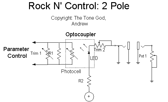
Figure 2
Not particularly exciting is it ? Oh well, thats how things go. One nice thing that to notice is the rocker pedal only needs two connections, ground and the control signal. This allows the use of standard mono 1/4 inch connectors. Heres a quick explanation of the parts in the circuit and their function.
R1: Sets the maximum resistance of the optocoupler. It should be the same value as the orignal control.
Trim 1: Trimmer version of above in case you want to set the maximum value by hand.
Photocell: Provides series resistance to control the effect’s parameter.
LED: Serves as the light source to control the LDR.
R2: Current limiting resistor for the LED.
Trim 2: Trim pot to set the maximum brightness of the LED thus the minimum value of the LDR.
Pot 1: Rocker pedal pot used to control the LED’s brightness.
Rock N' Control (3 Pole)
Up to this point we have be discussing how to control an effect’s parameter that uses serial resistance but sometimes the parameter in question uses all three connections on the pot. It is still possible to control this parameter but it will take a little more work.
A pot works when the shaft is turned causing the resistance between the wiper and one terminal end to lower while at the other terminal end the resistance increase at the same rate. In order to control a pot from remote using optocouplers a way to replicate this behavior is needed. The problem is that LDRs are series resistance devices that don’t have a center wiper which changes resistance towards the terminal ends proportionately.
Lets look at the pot in a different way. Instead of seeing the a pot as one resistor which has a wiper that can move to different positions tapping off the resistor (Figure 3) look at it as two resistors in series, making a center tap, with the resistors changing resistance in direct proportion to each other (Figure 4). Looking at it this way the two series resistors can be replaced with LDRs but this only solves the problem of the LDR not having a wiper. Emulating the proportional changing resistive behavior is the tricky part.

Figure 3
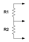
Figure 4
In order for the two resistor psuedo-pot to work each resistor must travel in opposite resistive directions but at the same rate. In Figure 4 if R1 decreases in resistance R2 must increase in resistance at the same rate. This emulates the wiper moving. This behavior would be difficult to achieve if using a mechanical variable resistive mechanism but since we are using LDRs the job is made much easier. All is needed to change the resistance of the LDRs is to adjust the brightness of the LEDs. In this case to get the behavior we are looking for one LED should increase in brightness while the other LED decreases in brightness at the same time and the same rate upon a change in the rocker pedal position.
Here is a circuit that can perform this function:
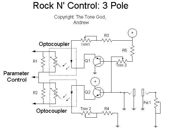
Figure 5
Above is the schematic for a three pole Rock N’ Control (Figure 5). Notice that the circuit still only needs two connections to the rocker pedal, ground and the control signal. You have to do the usually watch of Hfe, bias, etc. with the transistors. A description for each of the parts is as follows:
R1, R2: Sets the maximum resistance of the optocoupler. It should be the same value as the orignal control.
R3, R4: Current limiting resistor for the LED.
R5: Minimum bias value. Trim 1, Trim 2: Trim pot to set the maximum brightness of the LED. Used to balance LEDs brightness with each other.
Trim 3: Trim pot to set the bias point (center) for Q1 and Q2 so Pot 1 can sweep the full brightness of the LEDs.
Q1: PNP transistor, 2N3906. Any PNP transistor should work.
Q2: NPN transistor, 2N3904. Any NPN transistor should work.
Pot 1: Rocker pedal pot used to control the LED’s brightness.
This board could also be used for controlling dual pot LFOs as talked about in “A Single Pot Speed Control for LFO’s – Univibe, Trem Face, and Others” with one pot using some simple modification.
Other notes
There are some other benefits to using optocouplers. If the pot becomes scratchy the noise will not be heard in the audio signal since the parameter signal the optocoupler controls is isolated from the scratchy pot. So unlike when a wah pot has to be replaced because it became scratchy but otherwise still works the optocoupler won’t carry the noise over to the audio signal. Unless the problem is so bad that it causes a change in the pot’s resistive behavior the circuit will keep working as intended. This helps extend the life of the pots used in rocker pedals. I regularly use pots that have developed a mild scratch but are otherwise fine in rocker pedals that control optocouplers.
If you have a complete failure of the pot the optocoupler will simply default to it highest resistance thereby allowing the effect to continue to operate be it at its maximum resistive setting for the controlled parameter. The control pot can then be change without risk of changing the audio characteristics because the pot is isolated from the audio signal.
Further failures can be prevented by using a grounding jack so if the cable is removed the effect will default to its minimum resistive setting.
A full switching jack could also be used so you can set the default setting for the effect if the cable is removed. Better yet put a control on the effect box that will control the optocoupler when the cable is not plugged in thus you have the option of controlling the effect with either the rocker pedal or the panel control.
With the ability to control effect parameters from a far you can build all your effects into one unit, like say a rack mount enclosure, and route what parameters you want to actively control via optocouplers to a pedal board.
A footswitch to control logic based switching can be added to a rocker pedal if you use stereo 1/4 inch connectors using the third connection for the switch control. The logic switching should require a connection to ground to be activated. Can someone say “Wicked Switch” ?
Here is some more information on how to use optocouplers and adding expression control to effects from GEO:
Add an Expression Pedal to Any Effect
A Single Pot Speed Control for LFO’s – Univibe, Trem Face, and Others
LERA – Leslie Effect Rotor Adapter
