Skip to content

Wicked Switches

Intro

Electronic switching seems to have been somewhat misunderstood by the DIY community. There is little information available on the topic. Some people don’t understand how to do it properly. Other people have totally dismissed it as “bad” relating it to “Boss” style switching which is evil. I hope I can clear some things up with this article explaining how to use electronic switching.

For this article I’m going to focus on building a electronic DPDT switch with an LED indicator.

Check out R.G. Keen’s artical on CMOS switching for more helpful information. I won’t get too much in to how digital logic works in general just how I’m using it here. Consult your local search engine for information on using digital logic gates.

History

I have not bought a DPDT or 3PDT switch for many years. There are a number of reasons for this.

1. Hard to get
2. Expensive
3. Fail more easily

In the past the push switches that we see on pedals were not intended for either constant use or audio signals but for switching high voltages hence their size and strength. At the time these push switches were really the only solution for cheap and sturdy switching in effects. Thats is why they were chosen. Technology has moved on but nestolgic musicians still have a fascination with shiny metal push switches, problems and all. Let see if we can still satisfy that urge but secretly bring them into the present by putting some stuff under the hood.

Switching Options

Relays: Probably the only option that musicians will accept instead of push buttons since it basically a mechanical switch. Mechanical stuff seems to make musicians happy. Sometimes they require special switch arrangements. They can be expensive. If your using small self-contained relays that you bought I bet I can tell you what the insulating material is, nylon. Nylon is a good insulator but when it starts getting warm (like under lights, near tube amps, in a rack mount unit, weather) its insulative properties degrade rapidly. It might be better to “role your own” realys if this is this case. The only time I really would use relays is in high voltage/current switching situations like switching amp channels/cabs/etc.

FETs: It works. Its fairly cheap. Its used by many large pedal makers like Boss, DOD, Dunlop. It messes with your tone. This is the reason for the renew interest in true-bypassing. There are enough articles on this topic so I’ll leave it alone.

ICs: There are a number of ICs that can do analog audio signal switching. The most popular are the 4016, 4053, and 4066 which are part the digital logic family but are actually analog. They have excellent characteristics for audio signal switch. Good enough for our switching needs.

There are some specialized ICs for the specific task of audio switching. I tend to keep away from these since they can be expensive, hard to get, need special external circuitry, or colour the sound.

4016 vs. 4066

The differences between these ICs has not really been explained well for DIYers. Lets see if we can do something about that.

The 4016 and 4066 are both bilateral switches. By bilateral we mean that signals can go in both directions through the switch. Both have four SPST switches. Both share the same pinouts therefore they can be used to replace each other. The difference is that the 4016 has a higher internal resistance across the switch. This means a loss of signal fidelity. The 4016 is really meant for other types of switching and is not optimized for audio switching. The 4066 is much better for audio switching.

No matter which IC you choose to use you should use it at full supply voltage. The internal resistance of the switches increases when you use lower voltages. Audio problems can occur if you use them at the typical digital voltages of 3-5 volts. Since most effects use a 9v supply so use the full 9v. I have used them at as high as 15v with no problems.

When is 4xxx not a 4xxx ? For us when its not of the CD4xxx family. Some 4xxx do not have features that we need like the ability to run at higher voltages and buffering. The buffering we are talking about here is between the control input and switch itself. You wouldn’t want the control signal to get into your valuable audio signal. By JEDEC definition the CD4xxx family’s analog switches can handle the voltages we want and have buffering. If you see CD4016 or CD4066 without the “B” suffix (“B” = buffering) the “B” is implied since its part of the CD4xxx family.

Now thats cleared up…I think.

I haven’t played with the 4053 much. It has three SPDT switches but we only really need two for our purpose. It also has a few pins that you have to take care of which is not a big deal but its still something to keep in mind.

I prefer the CD4066 for audio switching and will continue through this article using this IC.

Wiring The 4066

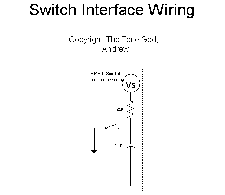
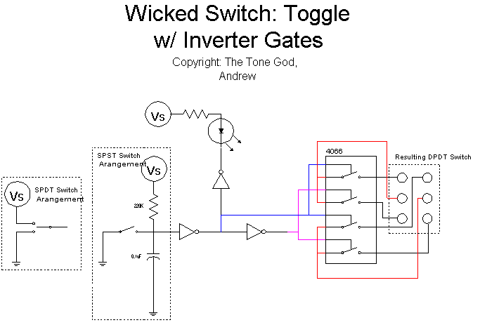
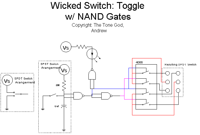
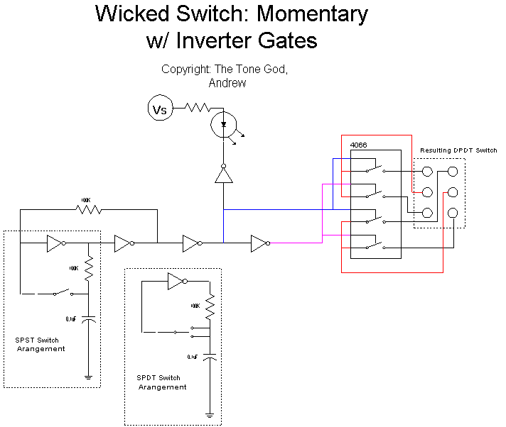
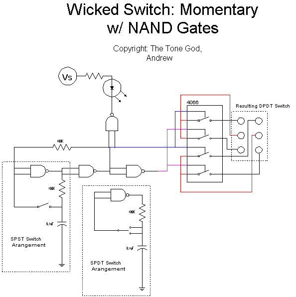
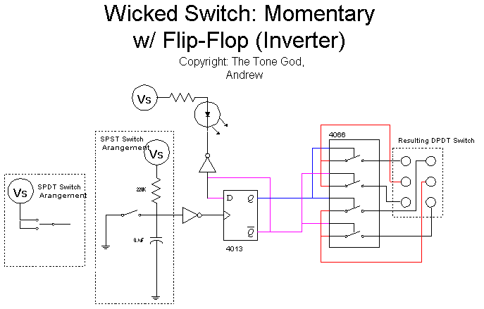
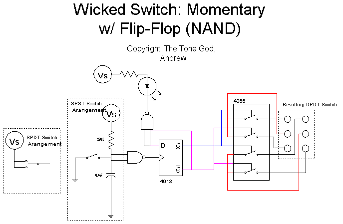
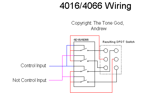
Use the 4066 is not that hard. As you can see by tying some pins together we can get what we are looking for. We could control the 4066 directly using a switch but can't have as many switch possibilities due to limitations of the switch. Notice that the state of one switching signal must be inverted from the other in order for the switch to operate as we intend. This is not tough to do if we use some other digital ICs.

Switch Control Logic

In order to control the 4066 properly from a mechanical switch we going to employ some other digital ICs. The main ICs we will be using are digital logic inverters. For the sake of flexibilty I will provide circuits to use both deidicated inverter ICs and NAND gates wired for inverting. Using inverters will allow us to generate both control signals from a mechanical switch that can drive the 4066 properly.

Mechanical Switch Interface Circuitry

Speaking of mechanical switches you may notice theres a RC network on the input. There are two reasons for this. If we are using a SPST switch we need to set the logic input at a level opposite of the state the switch will give on operation. The other use is mechanical switches don’t make clean connections when operated which can result in false input data so we smoothen the connection out by using the RC network. The capacitor charges through the resistor giving a high state at the gate’s input. When the switch is hit it discharges the capacitor to ground slowly until it reaches what the gate recognizes as a low state. This slow charge and discharge softens the rapid changes in state while the switch is operating thus reducing the amount of dirty data at the input. Using ICs with Schmitt triggers will also help.

With a SPDT switch you can either wire it up like a SPST or switch between high and low logic states manually. You may get some popping without the RC network though.

Schmitt Wha ?

The logic ICs that are used to control the 4066 are available with Schmitt triggers. Essentially a Schmitt trigger switches state at a higher voltage then normal gates allowing for some of the imperfect switching pulses from the mechanical switch to be tolerated thus reducing miss-triggering. The choice is yours as to which one to use. Non-schmitt ICs, 4049 (inverter) and 4011 (NAND) are easier to get but the Schmitt versions, 40106 (inverter) and 4093 (NAND), will play a little nicer with mechanical switches.

LED Indicator

Another advantage to using digital logic for control is that it is easy to use a spare logic gate to drive an LED as an indicator light. No real special wiring needed.

Wicked Switch (Toggle Version) Schematic

Here we have the complete schematic for the Wicked Switch. This should give you a toggle DPDT switch from either a SPST or SPDT toggle switch. What if all we have is momentary switches lying around ? Theres a way to do that too.

Momentary Switch Control Logic

If all you have lying around are momentary switches you can still get a DPDT switch. Unlike toggle switch that maintain it’s new state after operating momentary switches return back to its default state after operation so we need reverse and maintain the new logic state after the switch has cycled. This is done by using a “T” flip-flop which switches state on every clock pulse, the clock pulse being supplied in these case by the switch. Using some of the extra inverter gates and a few external components we can create a “T” flip-flop.

We could also use a dedicated flip-flop IC like the highly available 4013 (dual “D” flip-flop) with less external parts needed but you’ll need to fit in another IC in.

There are a few advantages of using momentary switches. It can be a footswtich (carling, arrow, mode, etc.), a “computer keyboard” style switch (Boss, DOD, Ibanez, etc.), or whatever else you want. This give alot of flexibility. You can also send control data from a number of switches allowing for multiple remote control points. If you use the version using the 4013 flip-flop all you need to do is tap the control wire to ground. Very easy wiring for switches, especially multiple switches.

Hopefully this will help out those who wish to explore electronic switching. Check out the download area for packages to make your own Wicked Switches.

Your Tone God,

Andrew

Copyright The Tone God 2024